V2 feedback : extrudeRotate
-
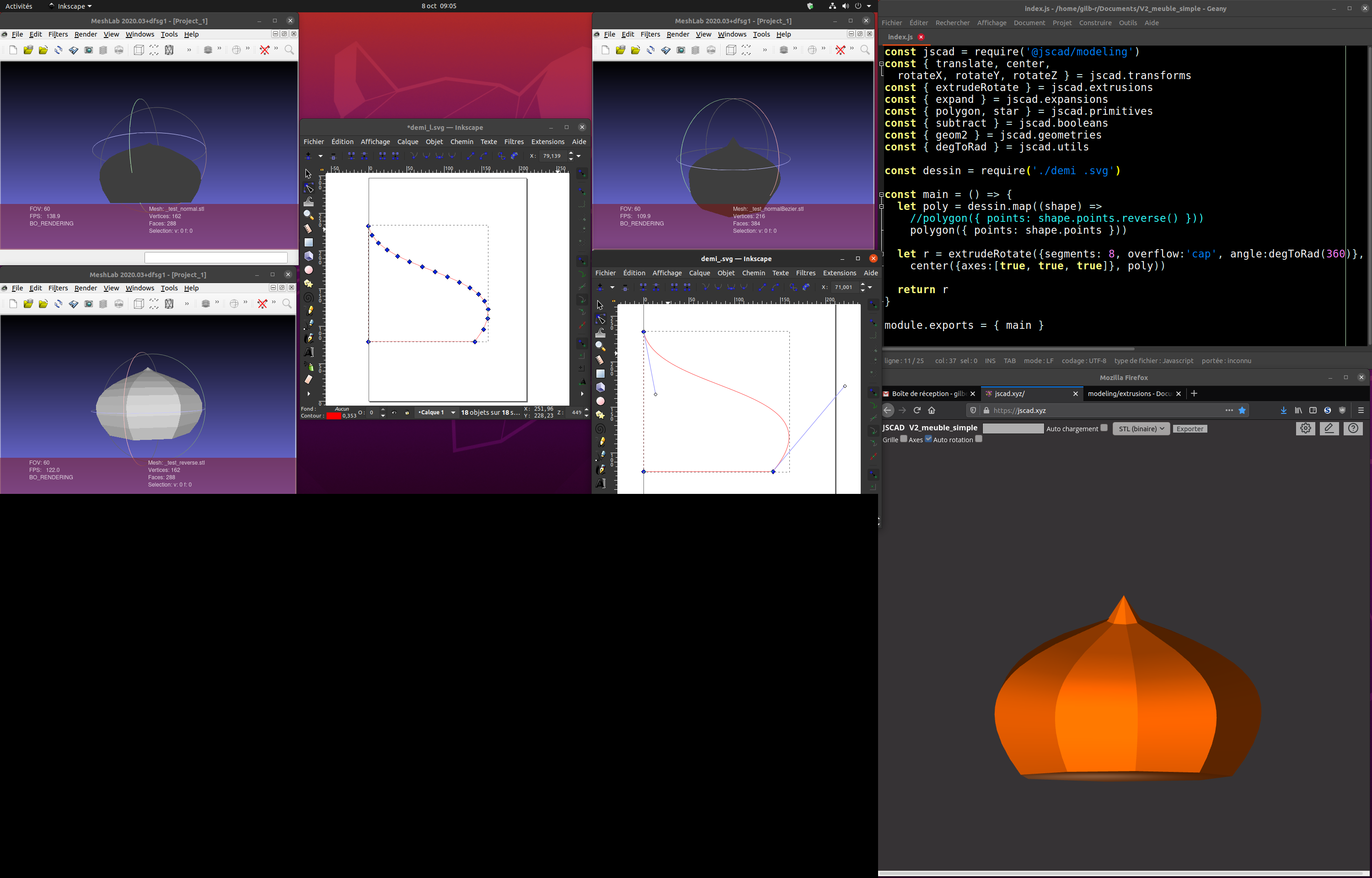
I tried to make a curved volume using extrudeRotate with a bezier curve (svg file) as input, but it didn't work (third meshlab window). So I replace the bezier by lots of lines, but it made the same (first meshlab window). By reversing points order when making the polygon (shape.points.reverse()), it was ok, but this operation result in an error with the bezier svg points. With bezier polygons, there is maybe a smarter way to reverse points ? maybe only reverse physical points and keep bezier control points order, but how ?
-
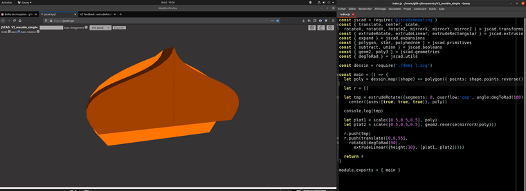
I tried to dig further this design and decided to only keep half revolution of the extrudeRotate and add an extrudeLinear to its flat end. Seems that extrudeRotate and extrudeLinear with the same input result in volumes of different scales. And mirrorX on this input gives a polygon that must be reversed to be correct. At first I tried to use the polygons from the extrudeRotate to do the extrudeLinear, but seems that it doesn't work with 3d polygons, I will try to 2d it as I have a function for that. Unfortunately, I don't see how to find the correct scale to align rotate and linear parts of this design.
This is very nice to be able to do such design even if for the moment it is not complete.
-
@gilboonet FYI, there's an issue with mirroring inside the renderer. the produced geometries are correct, but rendered incorrectly.
-
@gilboonet said in V2 feedback : extrudeRotate:
And mirrorX on this input gives a polygon that must be reversed to be correct.
Correct. By mirroring the CCW rotating geom2, the result is a CW rotating geom2.
-
@z3dev Do you know why extrudeRotate at 180° doesn't produce the same polygon as extrudeLinear (from the same polygon input) ? Or if there's a way to extrude a (flat) 3d polygon ?
-
@gilboonet can you attach the SVG file, or provide the set of points?
Both of the extrusion methods require 2D shapes that rotate CCW around Z. (You already know this.)
-
@z3dev the svg is here : https://github.com/gilboonet/gilboonet.github.io/blob/master/demos/demi_l.svg
What I'm trying to do is a composite volume made of half a revolution of extrudeRotate then extrudeLinear with the same shape. I was able to have both extrusion method return a volume, but they don't coincide.
Hello! It looks like you're interested in this conversation, but you don't have an account yet.
Getting fed up of having to scroll through the same posts each visit? When you register for an account, you'll always come back to exactly where you were before, and choose to be notified of new replies (either via email, or push notification). You'll also be able to save bookmarks and upvote posts to show your appreciation to other community members.
With your input, this post could be even better 💗
Register Login